Part list and download links at the bottom.
After idly wondering whether it would be possible to 3D print a flue pipe, the very first attempt produced a working whistle. So this seemed easy enough. Also, if I can make one whistle, certainly an organ is just a set of whistles of the correct lengths and a bunch of buttons?
So , I made a which allowed me to have a 7515 fan blow a steady stream of air into the candidate and tuned it to 880Hz, via two processes. For larger errors, I went by trial-and-error while varying the pipe length (actually the resonator length, i.e. the upper part), and ultimately fitted a function via gnuplot. For small errors below +-10Hz, the pipe has a 4mm hole at the top into which an M4 screw goes. The screw extends somewhat into the resonator and thereby changes the resonant frequency slightly.
You might notice the whistle extends into the test stand. This is because I extended the whistle model's bottom with a 0.2mm wall to prevent warping. It's easy to break off after printing. Similarly, the tip of the upper lip came out as a single (extremely instable) filament strand after slicing, which I manually broke off on each pipe. That process leads to a much sharper edge (and better tone) than all my attempts to get the printer to produce a sharp corner.
The next part I needed was a key to press -- which somehow needed to control the air flow into the pipe. A typical organ has some valve below the pipe. To actuate that however, I'd have needed some mechanisms which transferred the movement inside the higher-pressure part while being decently sealed.
Instead, I designed a which closes the outflow of the pipe. The key can simply hinge on the pipe itself. The STL (and the rendering) has the spring going through the pipe, but in reality that upper part would be bent slightly and press upon the pipe's outer wall. I printed the keys in PLA, which is not the best material for elastic parts, but after some tuning (including varying the spring width along its length) it seems to work without permanent bending.
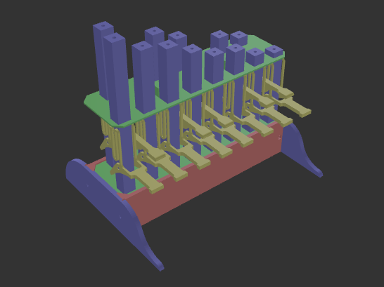
Next up was a which holds the entire octave of pipes. As it covered nearly my entire print bed and (likely due to slightly cooler edges of the bed) had a tendency to warp, I added a 0.2mm at the corners, which I broke and filed off after printing.
Adding it becomes clear that the back-row needs . The big disk-like area in the middle exists to ensure that edges from the springs (which sometimes bend a bit sideways) can always slide across a closed surface and will never get stuck at an edge from the back key, and vice versa, including when the back key is pressed down ().
The main body of the organ is formed by a (with mouse ears for warp-protection), which has a groove into which the fits. Later, this will be held in place by the , which in turn are screwed via M4 nuts and screws to the back and front wall.
My final assembly order was: Add M4 nuts in the inserts in the front and back plate, then press the fan into the back plate's inlet hole (both these steps might require some force and are best done with nothing else attached to the plates). Then, take the , and add (by sliding them onto the sockets). Next, snap on all the and -- it's easier in this order as the back keys are hard to snap onto the hinges when the front keys are in the way. Add the , the , and the . Keep the body in place via the , and screw them in place. Finally, slide the onto the pipes from the top and screw it into place (again M4 screws), it reduces the load on the somewhat fragile pipe sockets, when keys are pressed.
Finally, find a good voltage to run the fan at. I have a 5V fan, but am running it at 12.3V which seems to generate a good pressure for most of the pipes -- except the two highest ones, which work better with higher pressure (I might redesign them to accept the same pressure as the lower tones).